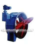
Tipping Sealing Butterfly Valve
manufacturer: Shanghai MeiYan Yi Pump & Valve Co., Ltd.
Eml: sales@1bengfa.com
Tel: +86 (21) 5640 2009
Mob: +86 138 1691 3072(WeChat Same Account)
product drawing

Tipping sealing butterfly valves
Usage and features
The series of tipping sealing butterfly valve is applied to the pipelines of the air of the ventilation and environment engineering of metallurgy, building materials, chemical industry, power plants and other industries or other gas, worked as the device of cutting off the gas flows. It can be composed with a variety of actuators to make up different performance devices.
Dimensions & constructral diagram

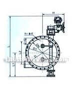
Tipping sealing butterfly valve constructral diagram(pic1)

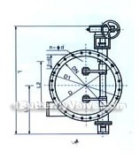
Tipping sealing butterfly valve constructral diagram(pic2)

Tipping sealing butterfly valve constructral diagram(pic3)

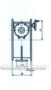
Tipping sealing butterfly valve constructral diagram(pic4)
Main connection dimensions
| ND | D | D1 | B | b | n-φd | L1 | L2 | L3 | d | H | RGD944H | RGD344H | |
| L | W | L | |||||||||||
| 400 | 540 | 495 | 350 | 18 | 16-φ22 | 298 | without frame legs | 816 | Z5-24 | 746 | |||
| 450 | 595 | 550 | 325 | 870 | Z10-24 | 800 | |||||||
| 500 | 645 | 600 | 400 | 20-φ22 | 350 | 920 | 850 | ||||||
| 600 | 755 | 705 | 20-φ26 | 408 | 1036 | Z15-24 | 966 | ||||||
| 700 | 860 | 810 | 450 | 20 | 24-φ26 | 460 | 1136 | 1085 | |||||
| 800 | 975 | 920 | 24-φ30 | 818 | 1216 | 1101 | |||||||
| 900 | 1075 | 1020 | 500 | 868 | 1316 | Z20-24 | 1201 | ||||||
| 1000 | 1175 | 1120 | 28-φ30 | 618 | 1516 | 1405 | |||||||
| 1100 | 1075 | 1220 | 550 | 22 | 668 | 1666 | 1506 | ||||||
| 1200 | 1375 | 1320 | 32-φ30 | 718 | 1766 | Z30-24 | 1606 | ||||||
| 1300 | 1475 | 1420 | 600 | 768 | 1220 | 400 | 30 | 790 | 1866 | 1716 | |||
| 1400 | 1575 | 1520 | 24 | 36-φ30 | 818 | 1290 | 840 | 1966 | 1816 | ||||
| 1500 | 1675 | 1620 | 650 | 878 | 1400 | 450 | 895 | 2126 | Z45-24 | 1956 | |||
| 1600 | 1790 | 1730 | 40-φ30 | 928 | 1470 | 945 | 2176 | 2006 | |||||
| 1700 | 1890 | 1830 | 700 | 26 | 980 | 1550 | 500 | 995 | 2330 | 2160 | |||
| 1800 | 1990 | 1930 | 44-φ30 | 1030 | 1620 | 1045 | 2380 | Z60-24 | 2210 | ||||
| 1900 | 2090 | 2030 | 750 | 1080 | 1720 | 550 | 33 | 1095 | 2480 | 2285 | |||
| 2000 | 2190 | 2130 | 48-φ30 | 1130 | 1800 | 1145 | 2700 | 2505 | |||||
| 2100 | 2305 | 2240 | 800 | 28 | 1180 | 1870 | 600 | 1200 | 2806 | 2611 | |||
| 2200 | 2405 | 2340 | 52-φ33 | 1238 | 1950 | 1255 | 2866 | Z90-24 | 2696 | ||||
| 2300 | 2505 | 2440 | 850 | 1288 | 2050 | 650 | 1305 | 2916 | 2715 | ||||
| 2400 | 2605 | 2540 | 56-φ33 | 1338 | 2130 | 1335 | 2966 | 2796 | |||||
| 2500 | 2705 | 2640 | 900 | 1388 | 2200 | 700 | 1405 | 3016 | 2846 | ||||
| 2600 | 2805 | 2740 | 60-φ33 | 1438 | 2270 | 1455 | 3086 | Z120-24 | 2916 | ||||
| 2700 | 2930 | 2860 | 950 | 1498 | 2380 | 750 | 1505 | 3186 | 3016 | ||||
| 2800 | 3030 | 2960 | 64-φ36 | 1545 | 2640 | 1565 | 3286 | 3116 | |||||
| 2900 | 3130 | 3060 | 1000 | 30 | 68-φ36 | 1590 | 2540 | 800 | 36 | 1615 | 3386 | 3216 | |
| 3000 | 3230 | 3160 | 1650 | 2610 | 1665 | 3486 | 3316 | ||||||
2、flange dimensions conform to the standard of GB91151-88.
3、please specify the angle if it is not installed horizontally, the valve can be designed and manufactured according to customers’ requests.
4、please note if you require the attachment, including the servo amplifier, electric operation, control box, matching flange, etc.


